
Nano Shades Troubleshooting Wizard
Interactive guide for diagnosing and resolving Nano shade issues
What issue are you experiencing?
Select the problem that best describes your situation.
What type of Nano shade do you have?
Choose the shade style that matches your installation. This helps us show you only compatible motor types.
What type of Nano shade do you have?
Identifying your shade type helps us provide accurate battery troubleshooting. Only certain shades support battery power.
This shade type doesn't support battery power
Battery-powered motors are only available for:
- Nano Box (V1 and V2)
- Nano Open Roll (with battery contact holders or V2 charging magnet)
Your shade type uses low voltage or line voltage motors only.
What type of Nano shade do you have?
Identifying your shade type helps us provide accurate physical/fabric troubleshooting guidance.
What type of Nano shade do you have?
Identifying your shade type helps us provide accurate ecosystem troubleshooting guidance.
What size is your Nano Box?
The size determines which motor series are compatible. Check your order documentation if unsure.
What size is your Nano Open Roll?
The size determines which motor series are compatible.
What size is your Nano Pocket?
The size determines which motor series are compatible.
What size is your Nano Pocket Duo?
The size determines which motor types and power options are available.
What size is your Nano Coupled Duo?
Coupled Duo shades come in 375 or 475 sizes.
Your Nano Box 275 motor type?
275 Box shades use 30 Series motors. Select how you control your shade.
Your Nano Box 375 motor type?
375 Box shades can use 30 Series OR 50 Series motors. Select your motor type.
30 Series: Smaller, supports battery/LV power, all motor types (Zigbee, RS485, RTS, PoE)
50 Series: Larger/stronger, LOW VOLTAGE ONLY for 375 size (RTS or RS485 only, no battery, no PoE)
Your Nano Box 475 motor type?
475 Box shades use 50 Series motors ONLY. Select RTS or RS-485.
All 475 size Nano shades use 50 Series motors. These motors support both LOW VOLTAGE DC and LINE VOLTAGE AC power. Only RTS and RS-485 motor types are available. No Zigbee, no PoE.
Your Nano Duo Box motor type?
Duo Box (275 only) supports Zigbee and RS-485. RTS is NOT available for this shade type.
Nano Duo Box shades only come in 275 size with 30 Series motors. RTS motors are NOT available for Duo Box configurations. Only Zigbee (Battery/LV) and RS-485 are supported.
Your Nano Coupled Box motor type?
Coupled Box (375 only) uses RTS or RS-485 motors with LV or AC power.
Nano Coupled Box shades only come in 375 size. They use RTS or RS-485 motors with either Low Voltage (DC) or Line Voltage (AC) power options.
Your Nano Open Roll 275 motor type?
275 Open Roll shades use 30 Series motors.
Your Nano Open Roll 375 motor type?
375 Open Roll can use 30 or 50 Series motors.
Your Nano Pocket 275 motor type?
275 Pocket shades use 30 Series motors.
Your Nano Pocket 375 motor type?
375 Pocket can use 30 or 50 Series. 50 Series = LV only for 375 Pocket.
Your Nano Pocket 475 motor type?
475 Pocket uses 50 Series ONLY (LV-DC or AC).
Your Nano Pocket Duo 275 motor type?
275 Pocket Duo: RTS (LV), Zigbee (LV), RS485. NO BATTERY options.
275 size Pocket Duo shades do NOT support battery power. Only low voltage options are available.
Your Nano Pocket Duo 375 motor type?
375 Pocket Duo: RTS (LV/AC) and RS485 (LV/AC).
Your Nano Pocket Duo 475 motor type?
475 Pocket Duo: RTS (LV/AC) and RS485 (LV/AC).
Your Nano Coupled Duo 375 motor type?
375 Coupled Duo: RTS (LV/AC) and RS485 (LV/AC).
Your Nano Coupled Duo 475 motor type?
475 Coupled Duo: RTS (LV/AC) and RS485 (LV/AC).
What motor type does your shade have?
Select based on how you control your shade.
Click "Help Me Identify My Motor" below to use our visual identification guide. We'll help you determine your motor type by wiring, buttons, and control method.
What type of motor needs limit adjustment?
If both your upper AND lower limits are off by approximately the same amount (6-8"), your motor did NOT lose its limits. This indicates the shade experienced a roll-over and lost a wrap of fabric on the tube. Click here for the fix.
Limits Shifted - Roll-Over Recovery
Limits are saved in the motor itself for all motor types. If both your upper and lower limits appear to have shifted by approximately the same amount (typically 6-8 inches), the motor has NOT lost its limits. What actually happened is the shade experienced a roll-over and lost a wrap of fabric on the tube.
How to Fix Shifted Limits After a Roll-Over
- Lower the shade past its current limit - Temporarily adjust or bypass the lower limit. Continue lowering until the roller tube is exposed. Go slowly!
- Inspect the fabric on the tube - Look for debris, bugs, loops, folds, or creases. Lowering to this point will release any of these issues.
- Verify fabric is properly seated - The fabric should be smooth and flat against the tube with no wrinkles.
- Re-set BOTH limits - Now that the fabric is properly positioned, set new upper and lower limits for your motor type.
- Test operation - Run the shade through several full cycles to verify both limits are correct.

Let's diagnose your Zigbee motor
We'll start by testing the motor directly.
Press the Motorhead Button (Quick Tap)
Find the small button on the motor head end cap and give it a quick tap.
Good news - your motor is working!
The motor responds to the Motorhead Button, so the issue is with communication, not the motor itself.
Try waking the motor from sleep mode
Motors are put into sleep mode for shipping. They don't go to sleep on their own.
Press and HOLD the Motorhead Button
Keep holding until the motor jogs once, then release.
Motor was in shipping sleep mode
The motor is now awake and should respond normally.
Is this a battery motor or hardwired?
Let's check the battery
Connect the charger
Attach the magnetic charger to the motor head. Look for a green flash on the LED when the charger connects - this confirms charging is happening.
Was this motor recently factory reset?
A motor with no limits set will NOT move at all - this is a common issue after factory reset.
Check power to the motor
Verify power is reaching the motor
Use a multimeter to check voltage at the motor's power wires. You should see ~24V DC.
Motor needs limits set
A motor with no limits will not move. Choose your method for setting limits:
Setting Zigbee Motor Limits via TaHoma Pro
This method connects directly to the motor via Bluetooth - no TRO.Y or Helen required. Useful for initial setup or when the Zigbee network isn't available.
Step 1: Put Motor in Bluetooth Mode
- Press the Motorhead Button 5 times rapidly
- Look for Fast Blinking Amber LED
- Motor is now discoverable via Bluetooth
Step 2: Connect with TaHoma Pro App
- Open the TaHoma Pro app on your mobile device
- Tap Add Device or the + icon
- Select Bluetooth as the connection method
- Your motor should appear in the list - tap to connect
Note: TaHoma Pro requires a Somfy dealer account. Account approval can take up to 24 hours.
Step 3: Set Limits in TaHoma Pro
- Once connected, tap Settings or the gear icon
- Select Limits or End Positions
- Set Upper Limit: Use the UP/DOWN controls to position the shade, then tap Set Upper Limit
- Set Lower Limit: Use the UP/DOWN controls to position the shade, then tap Set Lower Limit
- Tap Save or Confirm when done
Set the upper limit 1/4" to 1/2" below the cassette to prevent roll-overs. The fabric should NOT be fully wrapped around the tube.
Let's try a factory reset
Factory Reset (30 Series Zigbee)
Press and HOLD the Motorhead Button until the motor jogs 3 times, then release.
Note: This erases all settings including limits. You'll need to re-pair the motor and set limits.
Check Zigbee Signal Quality (SILQ)
Find the SILQ value in TRO.Y
- Open TRO.Y Integration Table Device Table
- Click on Helen Diagnostics
- Find the SILQ value for your motor
Signal looks good
SILQ 82+ means signal quality is optimal. Try testing with TaHoma Pro to isolate the issue.
Signal is marginal (SILQ 50-81)
SILQ 50-81 may work but can cause intermittent issues. Adding Zigbee routers will improve reliability.
Marginal signal can cause: missed commands, slow response, intermittent disconnects, and failed firmware updates.
Signal is too weak (SILQ <50)>
SILQ below 50 will cause serious reliability issues. You MUST add Zigbee routers to extend the mesh network.
With SILQ below 50, the motor will NOT function reliably. Commands may fail completely, and the motor may disconnect frequently. This must be fixed.
How to Improve Zigbee Signal with Routers
A Zigbee router is a powered device that extends the wireless mesh network. It receives signals from Helen and retransmits them to motors, acting as a signal repeater.
Router Placement Strategy
- Distance from Motor: Place router within 30 feet of the motor for best results
- Line of Sight: Minimize obstacles between router and motor (walls, metal objects reduce signal)
- Between Helen and Motor: Position router roughly midway between Helen controller and motor
- Avoid Metal Obstructions: Keep away from metal studs, HVAC ducts, electrical panels
- Power Outlet Required: Router must be plugged in continuously
Screen Innovations Zigbee Router: Purpose-built
for SI shades, guaranteed compatibility
Generic Zigbee 3.0 Routers: Most will work but
verify Zigbee 3.0 certification
Smart Plugs: Many Zigbee smart plugs act as
routers (check specs)
How Many Routers Do I Need?
- Minimum: 1 router per motor more than 40 feet from Helen
- Recommended: 2 routers per motor for redundancy
- Large Installations: Create mesh with routers every 30-40 feet
- Multi-Floor: Place router on each floor between Helen and motors
Adding Router to Network
- Plug in router at desired location
- Open TRO.Y web interface
- Go to Integration Table → Devices
- Click Discover or Add Device
- Put router in pairing mode (follow router's instructions)
- Wait for router to appear in device list (usually 30-60 seconds)
- Verify router shows "Online" status
The mesh network may take 15-30 minutes to optimize routing paths. Test motor SILQ again after this time to verify improvement.
Retest Signal Quality (SILQ)
Check SILQ After Adding Routers
- Wait at least 15 minutes after adding routers (mesh optimization time)
- In TRO.Y, go to Device Table
- Find your motor and check the SILQ value
- New SILQ should be significantly higher than before
82+: Excellent - no further action needed
50-81: Good - motor will work reliably
Below 50: Add more routers or reposition existing
ones
Signal Still Low After Adding Routers
Advanced Troubleshooting
- Verify router placement - Move routers closer to motor (within 20-25 feet)
- Check router status in TRO.Y - Ensure all routers show "Online"
- Add more routers - May need 2-3 routers to create strong mesh path
- Eliminate interference - Move away from WiFi access points, microwave ovens, baby monitors
- Check building materials - Metal studs, concrete, or multiple walls may block signal
Some buildings have too much RF interference or signal-blocking materials. If 3+ properly placed routers don't improve SILQ, consider:
- Relocating Helen controller closer to motors
- Using hardwired motors (RS-485) instead of Zigbee
- Consulting with RF specialist for site survey
Test with TaHoma Pro (Bluetooth)
Put motor in Bluetooth mode
- Press Motorhead Button 5 times rapidly
- Look for Fast Blinking Amber LED
- Open TaHoma Pro app and connect to the motor
Note: TaHoma Pro requires a Somfy dealer account.
Setting Zigbee Motor Limits
Your Nano shades came with limits set from the factory. Only adjust if the limits are incorrect.
Setting Limits via TRO.Y
- Open TRO.Y - Enter the IP address in your browser
- Navigate to Device Table - Go to Integration Table Device Table
- Find your motor and click Config
- Click Limits to open the limit adjustment interface
- Adjust Upper Limit: Click Adjust, use UP/DOWN to position, click Set
- Adjust Lower Limit: Click Adjust, use UP/DOWN to position, click Set
- Click Back when done and test operation
Let's diagnose your RS-485 motor
RS-485 motors are hardwired through Janus. We'll start by checking power.
Step 1: Check the Janus Power Supply
Look at the Janus power supply unit. Is the Blue LED on the power supply illuminated?
Janus Power Supply - Blue LED location
Important: The activity LEDs on the RJ45 ports can still be lit even when the power supply is OFF - they get power from TRO.Y's BUS line. Only the Blue LED on the power supply itself confirms shades are receiving power.
Janus power supply is not powered
Check these items:
- Power switch on the Janus power supply - Make sure it is switched ON
- Wall outlet - Verify the outlet has power
- Power cord connection - Check both ends are fully seated
- Circuit breaker - Ensure the breaker hasn't tripped
Check voltage at the motor
Measure voltage at the motor
- Set your multimeter to DC voltage
- Locate the motor's power wires (V+ and V-)
- Measure between V+ and V-
- Expected reading: 24-28V DC
Low voltage detected - WIRING IS THE MOST LIKELY CAUSE
You're getting low or no voltage at the motor. This is almost always a wiring issue.
If voltage drops when the shade is triggered, check the wiring FIRST above all else.
Follow the troubleshooting steps below to bypass the original wiring for testing:
- Run a temporary cable across the floor directly from Janus to motor
- Switch locations with a known working shade
- Direct plug-in test to eliminate all wiring
These elimination tests quickly identify if the problem is in the installed wiring.
Why Wiring Is Usually the Problem:
- Loose connections at Janus or motor terminals
- Damaged wire (pinched, cut, or corroded)
- Voltage drop over long wire runs
- Incorrect wire gauge (too thin)
- Poor quality connections
Check connections at Janus
Loose connections are the most common cause of low voltage.
At the Janus Hub:
- Check terminal tightness - Gently tug each wire. It shouldn't pull out.
- Look for loose screws - Screw terminals should be snug (don't overtighten)
- Check for oxidation - Green or white powder on terminals indicates corrosion
- Verify wire insertion - Wire should be inserted to the proper depth (about 1/4")
Test after tightening connections
Let's see if tightening the Janus connections fixed the issue.
Retest Voltage at Motor
Measure voltage at the motor terminals again. You should see 24-28V DC.
Check connections at the motor
Now let's check where the wires connect to the motor.
At the Motor:
- Check terminal type - Is it screw terminals or push-in connectors?
- Verify connections are secure - Tug gently on each wire
- Look for damage - Any cuts, pinches, or exposed copper near the motor?
- Check polarity - V+ (usually red) and V- (usually black) are on correct terminals
Test after fixing motor connections
Retest Voltage
Check voltage at the motor again. Should be 24-28V DC.
How many wires run to your motor?
RS-485 requires 5 conductors. Let's verify your wiring is correct.
Verify your 5-conductor wiring
Let's make sure each wire is connected to the right terminal.
V+ (Power Positive): Usually RED - carries 24V DC power
V- (Power Negative/Ground): Usually BLACK - power return
D+ (Data Positive): Usually WHITE or GREEN - RS-485 data signal
D- (Data Negative): Usually BLUE or YELLOW - RS-485 data signal
Shield/Ground: Usually BARE or GREEN - connect at Janus ONLY (not at motor)
Double-Check Polarity:
- V+ to V+ - Red wire should connect to V+ at both Janus and motor
- V- to V- - Black wire should connect to V- at both ends
- D+ to D+ - Data positive must match at both ends
- D- to D- - Data negative must match at both ends
- Shield - Should only be connected at Janus (leave disconnected at motor)
4-wire installation (missing shield)
RS-485 can work with 4 wires if the shield/ground isn't used, but it's not ideal.
The 5th wire (shield/ground) provides noise immunity. Without it, you may experience intermittent communication issues, especially on long runs (50 feet) or in electrically noisy environments.
Contact Inside Sales for Wiring Solutions
RS-485 motors need at minimum:
- 2 power wires (V+, V-) for 24V DC
- 2 data wires (D+, D-) for RS-485 communication
- 1 shield wire (recommended but optional)
With only 3 or fewer wires, you'll need to explore solutions with our Inside Sales team.
Our Inside Sales team can help you with:
- FONTUS devices - Converts 2-wire to 5-wire RS-485 using Power Line Communication
- Alternative motor options - Different motor types that may work with your existing wiring
- Wiring guidance - Best practices for running new conductors if needed
Phone: 512-832-6939 (Option 1)
Email: insidesales@screeninnovations.com
They can discuss FONTUS availability, ordering, and compatibility with your specific installation.
Test after correcting polarity
Retest Voltage and Motor Response
With correct polarity, you should now see 24-28V DC and the motor should respond to commands.
Multiple shades affected on same bus
When multiple shades on the same RS-485 bus stop working, it's usually a shared wiring or power issue.
A short circuit in ONE shade can affect ALL shades on that bus. To isolate the problem shade:
- Disconnect ALL shades from Janus
- Reconnect shades ONE at a time
- Test after each reconnection
- The problem shade is the one that causes all shades to fail when connected
Check power supply capacity
Multiple motors require adequate power supply capacity.
Each RS-485 motor draws approximately 1.5A at 24V DC
Formula: Number of motors × 1.5A = Minimum amperage needed
Examples:
- 3 motors: 3 × 1.5A = 4.5A minimum (use 5A or 6A supply)
- 5 motors: 5 × 1.5A = 7.5A minimum (use 8A or 10A supply)
- 10 motors: 10 × 1.5A = 15A minimum (use 16A or 20A supply)
How many motors are on this bus?
Is your power supply rated high enough?
Check the label on your power supply for its voltage and amperage rating.
Undersized power supply detected
An undersized power supply will cause intermittent failures, especially when multiple motors operate simultaneously. The power supply will appear to work but voltage will drop under load, causing motors to stop responding.
Solution: Upgrade to a properly-sized 24V DC power supply based on your motor count.
Try a wiring elimination test
These tests help determine if the problem is in the installed wiring or the motor itself.
Choose a Wiring Elimination Method:
Temporary test wire procedure
Run a Temporary Test Wire:
- Get a known good 5-conductor cable - Must be 18-22 AWG, rated for 24V DC
- Disconnect the existing wire from Janus (leave motor end connected)
- Run the test wire along the floor from Janus to the motor location
- Connect test wire at Janus - Match polarity (V+, V-, D+, D-)
- Connect test wire at motor - Disconnect old wire, connect new test wire
- Test motor operation - Does it work with the test wire?
Swap test with working shade
Swap Connections at Janus:
- Identify a working shade on the same RS-485 bus
- Label the wires so you can swap them back
- At Janus: Swap the wire connections (problem shade ↔ working shade)
- Test both shades
If problem follows the WIRE position: The wiring is bad
If problem follows the MOTOR: The motor is faulty
Direct plug-in test
Test Motor Directly at Janus:
- Temporarily remove motor from shade (if possible)
- Bring motor close to Janus
- Use a short patch cable (5-conductor, 3-6 feet long)
- Connect motor directly to Janus
- Test operation
Running a motor outside the shade tube can cause it to spin freely. Hold the motor securely and only jog it briefly.
Check motor status in TRO.Y
Check Device Table in TRO.Y
- Open TRO.Y in your browser
- Go to Integration Table Device Table
- Find your motor in the list
- Look at the Status column
Motor showing Offline
Check these items:
- Data wiring - Data+ and Data- must be connected correctly (swapped = no communication)
- Ground/shield wire - Must be connected for reliable data
- Address conflict - Two motors with same address will fail
- Run RS-485 Diagnostics - In TRO.Y Dashboard, run diagnostics to identify issues
Motor not in Device Table
Run RS-485 Discovery
- In TRO.Y, go to Integration Table Device Table
- Click Discover or Scan
- Wait for the scan to complete
- New motors should appear in the list
Test the motor from TRO.Y
Send a Test command
- In Device Table, find your motor
- Click the Test button
- Watch and listen - the motor should jog briefly
Group Command - Not All Shades Move
When a group of shades is triggered and not all shades move, this usually indicates insufficient voltage when the group command is sent.
The Janus power supply has two output sides:
- RJ45 Side: Outputs approximately 24V (lower voltage)
- Phoenix Connector Side: Outputs approximately 28V (higher voltage)
Issue: If shades are connected via the RJ45 side and a group is triggered, there may not be enough voltage for all shades to move simultaneously.
Solutions:
- Option 1: Use Phoenix Connector Side - Connect shades to the Phoenix connector side for 28V output
- Option 2: Use a SPIKE Device - A SPIKE maintains 28V while using the RJ45 side of the Janus
SPIKE is a power booster device that maintains 28V output when using the RJ45 connections on the Janus.
Learn more: SPIKE Reference Article
Identify Janus Connection Side
Look at your Janus power supply:
RJ45 Side: This side has RJ45 ethernet-style jacks (looks like network ports)
Phoenix Side: This side has green terminal block connectors with screw terminals
If your shades are connected with ethernet-style cables (RJ45), you're using the RJ45 side (~24V).
If your shades are connected with individual wires to screw terminals, you're using the Phoenix side (~28V).
Switch to Phoenix Side or Add SPIKE
Choose your solution:
Solution 1: Switch to Phoenix Connector Side
- Disconnect shades from RJ45 side
- Rewire shades to Phoenix connector side using terminal blocks
- This provides ~28V for better group command performance
Solution 2: Add a SPIKE Device
- Keep using RJ45 connections
- Install a SPIKE device inline
- SPIKE maintains 28V while using RJ45 side
- Reference: SPIKE Installation Guide
Motor jogs but won't move fully
When motor jogs (quick test movement) but won't complete full travel:
- Limits corruption - Motor thinks it's already at a limit
- Voltage drop - Insufficient power for sustained movement
- Mechanical obstruction - Something blocking shade travel
- Power supply capacity - Supply can't deliver enough current
Diagnostic Steps
- Check limits in TRO.Y - Look for value 65535 (indicates corruption)
- Test manual movement - Can you manually move the shade smoothly?
- Check voltage under load - Measure voltage while motor attempts to move
- Verify power supply rating - Does it provide enough amperage for your motor count?
If voltage drops below 20V when motor tries to move, your power supply is undersized or wiring has excessive resistance. Each motor typically draws 1-2A during movement.
Power supply insufficient
Power Supply Sizing
Calculate required capacity:
- Each RS-485 motor: ~1.5A peak, ~1A average
- Janus hub: ~0.5A
- Add 20% safety margin
Example: 5 motors + Janus = (5 × 1.5A) + 0.5A = 8A × 1.2 = 10A minimum
- Voltage sags below 20V during operation
- Motors jog but won't sustain movement
- Multiple motors fail to run simultaneously
- Random disconnects or resets
Solutions
- Upgrade power supply - Use higher amperage 24V DC supply
- Add second power supply - Split motors across two supplies
- Improve wiring - Use heavier gauge wire to reduce voltage drop
- Shorten wire runs - Keep power supply close to Janus/motors
Motor moves erratically
Erratic or stuttering movement usually indicates RS-485 data communication problems, not power issues.
RS-485 Data Line Troubleshooting
- Check data wiring - D+ and D- wires securely connected at Janus and motor
- Verify termination - Last motor in chain should have termination enabled
- Check for noise - Keep RS-485 wires away from AC power lines
- Test cable quality - Use shielded twisted-pair cable for data lines
- Check grounding - Shield/ground wire connected at one end only (Janus)
RS-485 maximum recommended distance: 4,000 feet (1,200m) total for entire bus. Longer runs may cause communication errors.
Address Conflicts
If multiple motors have same RS-485 address, they will interfere with each other:
- Check each motor's address in TRO.Y Device Table
- Addresses must be unique (typically 1, 2, 3, 4...)
- If duplicate found, reassign using TRO.Y Config
Check the motor's limits
View limits in TRO.Y
- In Device Table, click Config for your motor
- Click Limits
- Check the Upper and Lower limit values
If limits display as 65535, this indicates encoder or limit memory corruption. The motor needs a factory reset.
Factory Reset RS-485 Motor
Factory Reset via TRO.Y
- In Device Table, click Config for your motor
- Click Factory Reset
- Confirm the reset
- Wait for the reset to complete
- Run Discovery to re-add the motor
- Set new limits
Setting RS-485 Motor Limits
Setting Limits in TRO.Y
- Open TRO.Y - Enter the IP address in your browser
- Go to Device Table - Integration Table Device Table
- Find your motor and click Config
- Click Limits
- Adjust Upper Limit: Click Adjust, use UP/DOWN, click Set
- Adjust Lower Limit: Click Adjust, use UP/DOWN, click Set
- Click Back and test operation
Let's identify your RTS motor type
First, we need to determine which motor series you have. Look at the motor head where it connects to the shade tube.
Step 1: Check the Motor Head for Buttons
Look at the end of the motor (where it attaches to the shade tube). How many buttons do you see?
No buttons - let's check the power type
Motors without buttons are typically 50 Series AC (line voltage). Let's confirm by checking how it's powered.
How is your motor powered?
Look at where the power connects to your motor. What type of power connection do you see?
Check carefully for recessed buttons
You mentioned low voltage power but no visible buttons. Let's double-check for recessed buttons.
50 Series DC motors have three very small recessed holes on the motor head. They're easy to miss! You need the red programming tool (looks like a small hex key) to access them. Look very carefully at the motor head end cap.
Let's identify your RTS motor another way
No problem - we can identify your motor based on other characteristics.
30 Series: Used in 275 and 375 shades. Has one programming button. Can be battery or low voltage powered.
50 Series DC: Used in 375 and 475 shades. Has three recessed buttons (needs red tool). Low voltage powered only.
50 Series AC: Used in 375 and 475 shades. No buttons on motor head. Powered by 120V AC (wall plug or hardwired).
What size is your shade?
If you know your shade size, this can help narrow down the motor type.
Is your motor battery powered or wired?
For 375/475 shades, power type helps identify the motor series.
Check your motor's power connection
The power type is the most reliable way to identify 50 Series motors.
Look at the Power Connection
Follow the wires from your motor. What type of power source do they connect to?
Low voltage motor - check the motor size
Both 30 Series and 50 Series can be low voltage. The motor's physical size is the best indicator.
30 Series: Smaller, lighter motor (about 1.5" diameter)
50 Series: Noticeably larger, heavier motor (about 2" diameter) - for bigger/heavier shades
Test your 30 Series RTS motor
Step 1: Test with the Remote
Press UP or DOWN on your Somfy remote. Does the shade move?
Test your 50 Series DC RTS motor
Step 1: Test with the Remote
Press UP or DOWN on your Somfy remote. Does the shade move?
Test your 50 Series AC RTS motor
Step 1: Test with the Remote
Press UP or DOWN on your Somfy remote. Does the shade move?
Remote is working - what's the issue?
Remote is working - what's the issue?
Remote is working - what's the issue?
Remote is working - what's the issue?
Test the 30 Series motor directly
Tap the Motorhead Button
Find the small button on the motor head end cap and give it a quick tap. Does the motor move?
Motor works - remote needs pairing
The #1 cause of RTS remote issues is dead batteries. Use fresh, name-brand batteries before attempting to pair.
Try waking from sleep mode
Press and HOLD the Motorhead Button
Keep holding until the motor jogs once, then release.
What power type is your 30 Series motor?
Check low voltage power on 30 Series
Measure voltage at the motor
- Set multimeter to DC voltage
- Measure between the power wires
- Should read 24V DC (±10%)
Test the 50 Series DC motor directly
Use the Red Programming Tool
Insert the red tool into one of the three recessed buttons and press. Does the motor move?
Motor works - remote needs pairing
The #1 cause of RTS remote issues is dead batteries. Use fresh, name-brand batteries before attempting to pair.
Check low voltage power on 50 Series DC
Measure voltage at the motor
- Set multimeter to DC voltage
- Measure between the power wires
- Should read 24V DC (±10%)
Check AC power on 50 Series AC
These motors have NO physical buttons. Testing requires checking power directly.
Verify power at the motor
- Check the circuit breaker - is it ON?
- If hardwired, verify voltage at the junction box (~120V AC)
- If plugged in, verify the outlet has power
Test the motor directly
30 Series: Single button on motor head (275/375
shades)
50 Series DC: Three recessed buttons, requires
red tool (375/475 shades)
50 Series AC: No buttons on motor - skip to
power check
For 30 Series: Tap the Motorhead Button
Find the small button on the motor head end cap and give it a quick tap.
Motor works - remote needs pairing
The #1 cause of RTS remote issues is dead batteries. Use fresh, name-brand batteries before attempting to pair.
Try waking from sleep mode
Press and HOLD the Motorhead Button
Keep holding until the motor jogs once, then release.
What power type is your RTS motor?
Check low voltage power
Measure voltage at the motor
- Set multimeter to DC voltage
- Measure between the power wires
- Should read 24V DC (±10%)
Check AC power
Verify power at the motor
- Check the circuit breaker - is it ON?
- If hardwired, verify voltage at the junction box (~120V AC)
- If plugged in, verify the outlet has power
Which motor series needs factory reset?
Factory Reset - 30 Series RTS
Factory Reset Procedure
- Press and HOLD the Motorhead Button
- Continue holding until the shade jogs 3 times
- Release - motor is now factory reset
Note: This erases all limits and paired remotes.
Factory Reset - 50 Series DC RTS
The 50 Series DC has 3 recessed buttons that need to be pressed simultaneously.
Factory Reset Procedure
- Use the red tool to press and HOLD all 3 buttons (UP, STOP, DOWN) simultaneously
- Continue holding until the shade jogs 3 times
- Release - motor is now factory reset
Factory Reset - 50 Series AC RTS (2-10-2 Method)
A factory reset cannot succeed unless the motor is already in User Mode. If the motor is stuck in Programming Mode, the 2-10-2 reset will not work.
Step 1: Verify Motor is in User Mode
Tap the UP or DOWN button on the remote:
- User Mode: Shade moves continuously toward its limit
- Programming Mode: Shade moves in small increments only
If Stuck in Programming Mode - Return to User Mode First
- Press and HOLD MY/STOP until the shade jogs once
- If no jog, TAP the Programming Button on the back of the remote
- The shade should jog and return to User Mode
- If nothing responds, wait ~2 minutes for automatic recovery, then try again
Step 2: Perform the 2-10-2 Factory Reset
- Start with power ON to the motor
- Remove power for 2 seconds
- Re-apply power for 10 seconds
- Remove power for 2 seconds
- Re-apply power - the shade will begin to move
- When it stops moving, press and HOLD the Programming Button on the back of the remote until the shade jogs twice
Successful reset: Quick jog
Reset did NOT take: Shade moves more than a
jog
If unsuccessful, try again with different timing. Performing
the reset at the breaker is often easier than
unplugging at the junction.
AC Motor Stuck in Programming Mode
The motor may be stuck in Programming Mode if:
- UP + DOWN were accidentally held while at a limit (entered limit-adjust mode)
- The Programming Button was held too long, disabling normal operation
- The motor was factory reset unintentionally and has no limits
Try These Steps to Return to User Mode
- Tap the Programming Button on the back of the remote - shade should jog
- If no response, press and HOLD MY/STOP until the shade jogs
- Then tap the Programming Button again (another jog)
- Test by tapping UP or DOWN - shade should now move continuously
Holding the Programming Button in User Mode temporarily disables all motor control. If nothing responds after any button press, wait ~2 minutes for automatic recovery, then try again.
Power Cycle Recovery for AC Motor
This method uses AC power timing to force the motor back to factory default state.
Extended Power Cycle Procedure
- Disconnect AC power at the circuit breaker or unplug the motor
- Wait 60 seconds (full capacitor discharge)
- Reconnect power - motor will initialize
- Wait 10 seconds for boot-up completion
- Immediately test: Press UP or DOWN on remote - does motor respond?
A 60-second power disconnect clears all volatile memory including programming mode state. The motor will return to User Mode but may lose limits and pairing.
Manual Deprogramming Sequence
Force Unpair All Remotes
This will remove all paired remotes and return motor to factory state.
- Ensure AC power is connected
- Press and HOLD the Programming Button on your remote
- While holding, tap UP 5 times quickly
- While holding, tap DOWN 5 times quickly
- While holding, tap STOP/MY 3 times quickly
- Release the Programming Button
- Motor should jog twice if successful
After deprogramming, remote will NOT control motor. You'll need to pair it again using the RTS AC pairing procedure.
Full Factory Reset - Last Resort
This will erase ALL settings: limits, paired remotes, and motor configuration. You will need to re-pair remote and set all limits from scratch.
Complete 2-10-2 Factory Reset
- Power OFF at circuit breaker
- Wait exactly 2 seconds
- Power ON
- Wait exactly 10 seconds (count slowly: one-thousand-one, one-thousand-two...)
- Power OFF again
- Wait exactly 2 seconds
- Power ON and leave on
- Motor should jog twice within 10 seconds indicating factory reset
The 2-10-2 timing must be precise. If it doesn't work, wait 30 seconds and try again, counting more carefully.
Pair Remote - 30 Series RTS
Pairing Procedure
- Press and HOLD the Motorhead Button until the shade jogs once
- Release the button
- Briefly TAP the Programming Button on the back of the remote (do not hold)
- The shade will jog once to confirm pairing
Multi-channel remotes: Select the desired channel FIRST.
Pair Remote - 50 Series DC RTS
Pairing Procedure
- Connect power to the motor - the Red LED will turn ON (indicates no limits set)
- Using the red tool, press and HOLD UP + DOWN together until the shade jogs once
- Release - the remote is now paired
Pair Remote - 50 Series AC RTS
Pairing Procedure
- Apply power to the shade
- Press and HOLD UP + DOWN on the remote simultaneously until the shade jogs once
- Release - the remote is now paired
Set Limits - 30 Series RTS
Setting New Limits
- Use UP/DOWN to move shade to desired upper limit
- Press and release STOP/MY + DOWN together - shade will move down
- Press STOP near desired lower limit
- Fine-tune the lower limit using UP/DOWN
- Press and release STOP/MY + UP together - shade will move up
- Press STOP at the upper limit
- Press and HOLD STOP/MY until shade jogs once to save
- Briefly press the Programming Button on back of remote - shade jogs to confirm
Set Limits - 50 Series DC RTS
LED ON (solid red): Motor does NOT have limits
set
LED OFF: Motor has limits set
Setting New Limits (Red LED should be ON)
- Use UP/DOWN to move shade to desired upper limit
- Press and release STOP/MY + DOWN together - shade will move down
- Press STOP near desired lower limit
- Fine-tune the lower limit using UP/DOWN
- Press and release STOP/MY + UP together - shade will move up
- Press STOP at the upper limit
- Press and HOLD STOP/MY until shade jogs once to save
- The Red LED should turn OFF - confirms limits are set
Set Limits - 50 Series AC RTS
Setting New Limits
- Use UP/DOWN to move shade to desired upper limit
- Press and release MY/STOP + DOWN together - shade will move down
- Press MY/STOP near desired lower limit
- Fine-tune the lower limit using UP/DOWN
- Press and release MY/STOP + UP together - shade will move up
- Press MY/STOP to stop at upper limit
- Press and HOLD MY/STOP until shade jogs once to save
- Press and release the Programming Button - shade jogs to finalize
Reverse Motor Direction
Reverse Direction
- Press UP on the remote to confirm direction is wrong
- Press and HOLD STOP/MY until the shade jogs once
- Test again - UP should now move the shade up
Intermittent Response / Range Issue
Troubleshooting Steps
- Replace remote batteries - This is the #1 cause of range issues
- Check for RF interference - LED lighting, electronics, or other RF devices nearby
- Check antenna position - The motor's antenna should be fully extended
- Test from different locations - Determine if it's a specific spot or general range issue
Adjusting RTS Limits
Adjusting a Single Limit
- Move the shade to the current limit you want to adjust
- Press and HOLD UP + DOWN together until the shade jogs once
- Use UP and DOWN to move the shade to the new desired position
- Press and HOLD STOP/MY until the shade jogs once to save
Let's diagnose your PoE motor
PoE motors MUST have:
1. SI IP Bridge - Converts between IP network
and motor communication
2. TRO.Y - Gateway for control and configuration
If you don't have both, the PoE motors will not function.
Step 1: Check the SI IP Bridge
Is the SI IP Bridge powered on with network LEDs showing activity?
SI IP Bridge Diagnostics
The SI IP Bridge has multiple status LEDs:
- Power LED - Should be solid green
- Network/Link LED - Should show activity (flashing or solid)
- Status LED - Indicates bridge operational state
Check LED Status
Look at your SI IP Bridge and identify which condition matches:
IP Bridge Power Issue
Power Supply Troubleshooting
- Check power adapter - Is it plugged into a working outlet?
- Test the outlet - Plug in another device to verify outlet works
- Check power cable - Is it fully inserted into the IP Bridge?
- Try different outlet - Use a known-good outlet
- Inspect power adapter - Look for damage or bent prongs
SI IP Bridge requires 12V DC, 1A minimum. Using incorrect power adapter will cause issues or damage.
IP Bridge Network Issue
Network Connectivity Troubleshooting
- Check Ethernet cable - Is it firmly connected at both ends?
- Verify switch port - Is the port active? Try different port.
- Test cable - Try a known-good Ethernet cable
- Check switch LEDs - Does the switch show link activity for this port?
- Verify network - Is the switch powered and operational?
Connection: IP Bridge must connect to same network
as TRO.Y
Cable: CAT5e or better Ethernet cable
Network: Standard Gigabit or Fast Ethernet (100Mbps
minimum)
Check IP Bridge in TRO.Y
Verify Bridge Status in TRO.Y
- Open TRO.Y web interface
- Navigate to Integration Table → Devices
- Look for SI IP Bridge in the device list
- Check its Status - should show "Online"
- Verify IP Address - should be on same subnet as TRO.Y
Not Found in TRO.Y? Run device discovery
Wrong Subnet? TRO.Y and IP Bridge must be on
same network (e.g., both 192.168.1.x)
Offline Status? Check firewall or VLAN configuration
Advanced Network Troubleshooting
Network Configuration Checks
- DHCP vs Static IP - IP Bridge typically uses DHCP. Check DHCP server is active.
- Subnet Mask - TRO.Y and IP Bridge must be on same subnet (typically 255.255.255.0)
- VLAN Configuration - If using VLANs, both devices must be on same VLAN
- Firewall Rules - Some routers block inter-device communication
- Port Isolation - Check if switch has port isolation enabled (disable it)
These are advanced networking concepts. If you're not comfortable with network configuration, contact your IT support or use the Eco-System wizard for detailed networking guidance.
Check PoE power delivery
Check the PoE switch port
- Look at the switch port where the motor's Ethernet cable connects
- The port LED should indicate a valid link
- Check if PoE is enabled on that port
Check motor status in TRO.Y
Check Device Table
- Open TRO.Y in your browser
- Go to Integration Table Device Table
- Find your PoE motor in the list
- Check the Status column
PoE motor showing Offline
Check these items:
- SI IP Bridge status - Is the bridge online in TRO.Y?
- Run discovery - In Device Table, click Discover
- Check network path - IP Bridge and motor must be on same network segment
- Try a different port/cable - Rule out physical issues
Test the PoE motor
Send a Test command
- In Device Table, find your PoE motor
- Click the Test button
- Watch and listen - the motor should jog briefly
Setting PoE Motor Limits
Setting Limits in TRO.Y
- Open TRO.Y in your browser
- Go to Device Table - Integration Table Device Table
- Find your motor and click Config
- Click Limits
- Adjust Upper Limit: Click Adjust, use UP/DOWN, click Set
- Adjust Lower Limit: Click Adjust, use UP/DOWN, click Set
- Click Back and test operation
Nano Box - Which version do you have?
V1 and V2 Box shades have different battery charging systems. Look at the end cap screws.
Visual Identification:
Nano Box V1: Each end cap has 2 screws on the back + 1 screw on the top (3 visible screws per end cap)
Nano Box V2: Both end caps have a small hole on the outside end with a recessed 3/32" hex screw (1 recessed screw per end cap)
Nano Open Roll - How does the battery connect?
Open Roll battery motors have two different connection methods depending on the version.
Visual Identification:
Nano Open Roll V1 - Battery Contact Holders: Two spring-loaded metal contacts (pogo pins) in the mounting bracket
V1 Bracket:
V1 Motor Head with Contact Holder (small black part):
Nano Open Roll V2 - Charging Magnet: Wire from motor connects to a plug inside motor head, magnetic charger on end cap
V2 Bracket:
V2 Motor Head:
Open Roll Battery Contact Holder Issues
V1 Open Roll motors use spring-loaded battery contact holders in the mounting bracket.
Poor connection: Contacts not making solid connection with motor end cap
Misalignment: Contacts bent or not aligned with motor contact points
Degradation: Older versions - contact holders can disintegrate and need replacement
Troubleshooting Contact Holders:
- Inspect the contacts: Look for two spring-loaded pogo pins in the mounting bracket
- Check for damage: Contacts should be intact, not broken or crumbling
- Test spring pressure: Gently press each contact - should have firm spring resistance
- Check alignment: Contacts should align with matching points on motor end cap
- Push contacts toward end cap: Sometimes contacts need to be repositioned closer to ensure better connection
If contacts seem loose or not making good connection, gently push the contact holders toward the end cap to ensure better pressure on the motor's contact points. This can resolve intermittent charging or odd jogging behavior.
What symptom are you experiencing?
Reposition and clean the contacts
Contact Adjustment Procedure:
- Clean the contacts: Use isopropyl alcohol on both the pogo pins in the bracket AND the contact points on the motor end cap
- Check spring pressure: Press each pogo pin - should spring back firmly
- Gently push contacts toward end cap: If there's any gap, carefully push the contact holder closer to ensure firm pressure
- Verify alignment: Contacts should be centered on the motor's contact points
- Test the shade: Operate the motor and observe for improved behavior
Poor electrical connection from loose contacts can cause:
- Intermittent or failed charging
- Erratic jogging or stuttering movement
- Motor stopping mid-travel
- Reduced battery runtime
Contact holders need replacement
If the battery contact holders are broken, crumbling, or damaged, they must be replaced. This is especially common with older V1 Open Roll shades where the contact holder material has degraded over time.
To order replacement battery contact holders, contact our Inside Sales Team:
Phone: 512-832-6939 (Press Option 1)
Information to Provide:
- Shade model (Nano Open Roll)
- Shade size (275 or 375)
- Description of damage to contact holders
- Photos if possible
Nano Duo Box - Battery Troubleshooting
Nano Duo Box shades use Zigbee Battery motors only (V2 design with charging magnet).
All Nano Duo Box shades with battery power use V2 motors with:
- Charging magnet with plug connection
- Zigbee wireless control only
- Two independent motors (one per shade)
Identify V1 vs V2
Look at the end caps of your shade. How are they fastened?
Visual Identification:
Nano V1: Each end cap has 2 screws on the back + 1 screw on the top (3 visible screws per end cap)
Nano V2: Both end caps have a small hole on the outside end with a recessed 3/32" hex screw (1 recessed screw per end cap)
Nano V1 - What's the charging issue?
Check LED on Charger Transformer
Look at the transformer (power adapter) that's plugged into the wall. What color is the LED?
Red LED: Battery is dead or low (charging needed)
Green LED: Battery is approximately 75% charged or higher
Transformer shows Red - Battery is low
A red LED on the transformer indicates the battery is discharged or has low charge. This is normal operation.
Allow time to charge: Leave charger connected for 2-4 hours and re-check.
Transformer shows Green but shade is dead?
If the transformer LED is green (indicating ~75%+ charge) but the shade is not responding, the charger is likely not making proper contact with the battery.
This indicates a charging connection problem, NOT a dead battery.
Troubleshooting Steps:
- Verify magnetic charger is firmly attached to end cap charging contacts
- Check for debris or damage on end cap charging points
- Inspect charger magnet contacts for damage or dirt
- For V2 motors: Check internal plug connection inside motor head
Attach the charger - what do you see?
Place the magnetic charger on the end cap's charging contacts and observe the LED.
Charging is working correctly
A flashing green LED means your shade is actively charging. This is normal operation.
Charging time: Typically 2-4 hours for a full charge from empty.
Battery is fully charged
A solid green LED means your battery is at 100% charge. This is normal.
No LED - have you tried a different outlet?
Before checking the shade, let's rule out a power outlet issue.
Sometimes the issue is simply a dead outlet, tripped breaker, or loose plug connection. Try plugging the transformer into a different outlet that you know works (like one with a lamp plugged in).
Is this a new installation?
V2 charging magnets can become disconnected during shipping.
On Nano V2 shades, the charging magnet connector can become unplugged during shipping. This is the #1 cause of V2 charging failures on new installations.
Let's check the simple things first
Step 1: Clean the Charging Contacts
Use isopropyl alcohol on a cloth to clean:
- The charging contacts on the shade's end cap
- The magnetic charger's contact points
Reattach the charger. Does the LED light up now?
Is the charger working?
Let's verify the charger itself is functional.
Step 2: Test the Charger
- Check that the charger's power adapter is plugged into a working outlet
- Try a different outlet to rule out power issues
- If you have another Nano V2 shade, test the charger on it
Clean the charging contacts
Contact Cleaning Procedure:
- Use isopropyl alcohol (70%+ concentration) on a lint-free cloth
- Clean the shade's charging contacts on the end cap
- Clean the charger's magnetic contact points
- Let dry for 30 seconds
- Reattach charger and check for LED
How long does the battery last?
Nano batteries should last several months on a full charge with typical shade use (1-2 cycles per day).
Typical use (1-2 cycles/day): 6-12 months per charge
Moderate use (3-5 cycles/day): 3-6 months per charge
Heavy use (10+ cycles/day): 1-2 months per charge
Battery degradation: Capacity decreases over time (3-5 years typical lifespan depending on usage)
Battery draining too quickly
- Age: Batteries lose capacity after 3-5 years depending on usage
- Temperature: Extreme heat or cold reduces battery performance
- Heavy use: Frequent cycling drains battery faster
- Battery health: May need replacement if battery is 3+ years old
Important: Batteries are built into the motor assembly. Replacing the battery means replacing the entire motor unit.
To order a replacement motor, contact our Inside Sales Team:
Phone: 512-832-6939
(Press Option 1)
Email:
insidesales@screeninnovations.com
Nano V2 Charging Magnet Reconnection
Nano V2 end cap screws have REVERSE THREADS. Turn CLOCKWISE to loosen, COUNTER-CLOCKWISE to tighten. Going the wrong direction will damage threads!
Disassembly - Access Charging Magnet PCB
- Identify the motorized end cap - This is the end with visible motor components
- Locate recessed screw - On the outside end of the motor end cap, find the small recessed hole
- Insert 3/32" hex key - Use correct size to avoid stripping
- Turn CLOCKWISE to loosen - Remember: reverse threads! Loosen approximately 3-4 full turns
- Do NOT remove screw completely - Just loosen enough for fascia to release
- Gently snap open fascia - Pull motorized end cap fascia away from cassette body
- Locate charging magnet PCB - Small circuit board with magnet attached, near end cap
The charging magnet PCB has a small white connector plug that inserts into a socket on the motor head. If unplugged, you'll see:
- White plug hanging loose attached to short wire from magnet PCB
- Empty white socket on motor head
- Magnet may be rotated or out of position
Reconnection Steps
- Identify plug and socket - Plug has small pins, socket has corresponding holes
- Align plug orientation - Plug only fits one way (keyed connector)
- Gently insert plug - Push straight in until you feel/hear a click
- Verify seated - Gently tug on wire - plug should NOT pull out
- Check magnet position - Magnet should be flush with or slightly protruding from end cap surface
Reassembly
- Align fascia clips - Position end cap fascia to cassette body
- Press firmly to snap closed - Should hear/feel clips engage
- Tighten screw COUNTER-CLOCKWISE - Reverse threads! Snug but don't overtighten
- Test charging - Attach charger and check for LED activity
Flashing Green: Magnet reconnected correctly
- shade is charging
Solid Green: Battery was already full - working
correctly
No LED: Check plug connection again or verify
charger is working
If plug keeps falling out or won't click in:
- Check for damage to pins or socket
- Ensure plug is fully inserted (requires firm pressure)
- Verify you're using correct socket (motor may have multiple connectors)
- Contact support if connector appears damaged
Magnet Connected But Still No Charging
Additional Checks
- Verify charger works - Test with known-good Nano V2 shade if available
- Check charger contact alignment - Magnet should align perfectly with charger contacts
- Test different outlet - Verify charger's power adapter is plugged in
- Inspect magnet contacts - Should be clean and not recessed too deep
- Check battery connection - Battery may have separate connector inside motor head
If battery has been completely discharged for extended period (months), it may not accept charge. Lithium batteries can enter "deep discharge protection" mode and require special recovery or replacement.
Important: Batteries are built into the motor assembly. Replacing the battery requires replacing the entire motor unit.
To order a replacement motor, contact our Inside Sales Team:
Phone: 512-832-6939
(Press Option 1)
Email:
insidesales@screeninnovations.com
Nano Box - What physical issue are you experiencing?
Nano Open Roll - What physical issue are you experiencing?
Nano Pocket - What physical issue are you experiencing?
Duo Shade - What physical issue are you experiencing?
Duo shades have two independent shades in the same housing.
Coupled Shade - What physical issue are you experiencing?
Coupled shades have two or more shades connected together.
What physical issue are you experiencing?
Coupled Shade Installation Tips
Key installation steps to ensure proper coupled shade operation.
Installation Procedure:
- Bracket Placement: Install mounting brackets 4-6 inches from jamb. Ensure brackets are level and planar before proceeding
- Start on Idler Side: Always begin mounting the back extrusion on the idler (non-motor) side first
- Connect Extrusions: Slide extrusion sections together using the connecting pins. Tighten and lock down once aligned and centered
- Coupling Shades: Insert shade on idler side first. Push until you hear a click — this confirms coupling. Verify by rotating: both shades should move together
- Cycle After Install: Deploy all shades to lower limit, then retract. This ensures fabric is tight on the roll. Use SDN wall switch or RTS remote
Coupled Shades - Hembar Alignment & Leveling
Are the hem bars out of level after cycling the shades?
Common Issue: Too much tension on the couplers can cause binding noise and uneven operation.
The couplers between bands can be adjusted to reduce tension, which will help eliminate binding between the shades.
Hembar Leveling Procedure
Follow these steps to level uneven hembars on coupled shades.
Leveling Steps:
- Deploy Shade Slightly: Lower the shade a few inches to give yourself room to work and better visibility
- Uncouple the Shade: To access the inner idler, you'll need to uncouple. Pull gently — you'll feel resistance as it disengages
- Slide Out Idler: Remove the idler to expose the adjustment teeth
- Rotate to Adjust: Each marking on the teeth = 1/16 inch. Rotate toward you to raise that side of the hembar
- Recouple & Cycle: Slide idler back in, recouple the shade (listen for click), and cycle to verify level
Make small adjustments (1-2 markings) and cycle between each to avoid over-correction. Use a level or straight edge to verify alignment.
For detailed installation instructions with visual references, see the Nano Coupled Box Installation Guide - Leveling the Hembars
Band Alignment (Coupled Pocket Only)
For Coupled Pocket configurations: Ensure each band is perfectly in line with all other bands.
Band Alignment Procedure:
- Start at motor side: Begin alignment check from the motor-side shade
- Check each band: Verify that each shade's band aligns perfectly with adjacent bands
- Adjust as needed: Reposition any misaligned bands to ensure perfect alignment across all units
- Verify clearances: Ensure each band has proper clearance and isn't rubbing against adjacent components
Coupler Tension Adjustment
Too much tension on the couplers can cause binding noise and uneven operation.
Tension Adjustment Procedure:
- Check tension: Feel the tension on the coupler bands between shades
- Reduce tension if needed: Adjust the couplers to reduce excessive tension between the bands
- Test operation: Run all shades to verify smooth, synchronized movement without binding
What physical issue are you experiencing?
Side Channel Issues
Side channels are an optional accessory that can be added to any Nano shade type (Box, Open Roll, or Pocket) to guide fabric and prevent drift.
Side channels are an optional fabric guidance system - NOT specific to any particular shade type. They can be installed on any Nano shade configuration.
Common Issues:
- Fabric binding or catching in channel
- Noise from fabric rubbing
- Shade stops mid-travel
- Channel misalignment
For complete side channel installation instructions and troubleshooting guides, see:
What's happening with your side channels?
Fabric binding in side channels
Common Causes of Binding:
- Debris in channel: Dust, construction debris, or fabric fibers can cause catching
- Channel misalignment: Channels not parallel or level with roller
- Fabric edge damage: Frayed or damaged fabric edges catch more easily
- Excessive tension: Fabric pulled too tight against channels
- Improper installation: Channels too close to roller or incorrect spacing
- Clean the channels: Use compressed air or soft brush to remove debris from inside channels
- Inspect fabric edges: Look for fraying, damage, or irregularities along fabric edges
- Check alignment: Channels should be perfectly vertical and parallel to each other
- Measure spacing: Verify channels are correct distance apart for shade width
- Test without power: Manually lower shade slowly to identify binding point
Noise from side channels
Diagnosing Channel Noise:
Noise from side channels is usually caused by:
- Fabric rubbing: Fabric pressing too hard against channel walls
- Dry channels: Lack of lubrication causes friction noise
- Channel vibration: Channels not securely mounted to wall
- Fabric edge condition: Rough or damaged edges create more friction
- Clean channels thoroughly: Remove all debris and dust
- Apply dry lubricant: Use silicone spray or dry PTFE lubricant (NOT oil-based) inside channels
- Check mounting: Ensure channels are securely fastened to wall with no movement
- Inspect fabric: Smooth any rough edges or replace if severely frayed
- Adjust spacing: If channels are too close together, fabric may be under excessive pressure
Do NOT use oil-based lubricants! Oil attracts dust and will make the problem worse over time. Use only dry silicone or PTFE spray designed for fabric applications.
Shade stops mid-travel in channels
Why Shade Stops:
When shade stops partway down, it's usually because:
- Severe binding: Fabric completely caught on obstruction
- Motor overload protection: Motor detects excessive resistance and stops
- Fabric bunching: Fabric gathering or folding inside channel
- Foreign object: Something lodged in channel blocking fabric
If shade is stuck, do NOT keep operating the motor. This can damage the motor or fabric. Manually retract shade and identify the obstruction.
Recovery Steps:
- Stop operation: Do not continue trying to operate the shade
- Manually retract: Carefully pull fabric back up to free position
- Inspect channels: Look for visible obstructions, damage, or debris
- Check fabric path: Ensure fabric is feeding straight into channels, not twisted
- Test slowly: Lower shade slowly by hand to identify binding point
- Remove obstruction: Clear any debris or correct alignment issue
Side channel misalignment
Alignment Issues:
Proper channel alignment is critical for smooth operation:
- Vertical alignment: Channels must be perfectly plumb (vertical)
- Parallel spacing: Channels must be same distance apart from top to bottom
- Level with roller: Channel opening must align with fabric coming off roller
- Wall mounting: Channels must be securely fastened without gaps or movement
Realigning side channels requires precision tools and may involve wall anchors. If channels are significantly misaligned, contact support or a professional installer to avoid damage to walls or shade system.
Quick Alignment Check:
- Use level: Place level against each channel - should be perfectly vertical
- Measure spacing: Measure distance between channels at top, middle, and bottom - should be identical
- Check mounting: Press on channels - should not flex or move
- Visual inspection: Stand back and look at channels from a distance - should appear parallel
Identify Nano V1 vs V2
Look at the end caps of your shade. How are they fastened?
Visual Identification:
Nano V1: Each end cap has 2 screws on the back + 1 screw on the top (3 visible screws per end cap)
Nano V2: Both end caps have a small hole on the outside end with a recessed 3/32" hex screw (1 recessed screw per end cap)
Identify Nano Open Roll V1 vs V2
Open Roll V1 and V2 differ in their battery connection method (if battery-powered).
Visual Identification:
Nano Open Roll V1 - Battery Contact Holders: Two spring-loaded metal contacts (pogo pins) visible in the mounting bracket
V1 Bracket:
Nano Open Roll V2 - Charging Magnet: Clean bracket with no contact holders, magnetic charger on end cap
V2 Bracket:
What type of Nano shade do you have?
Different shade types have different noise causes and solutions.
Is this a Nano V2 Box?
V2 boxes have removable fascia that makes noise diagnosis easier. Look at the end cap screws.
Visual Identification:
Nano Box V1: Each end cap has 2 screws on the back + 1 screw on the top (3 visible screws per end cap)
Nano Box V2: Both end caps have a small hole on the outside end with a recessed 3/32" hex screw (1 recessed screw per end cap)
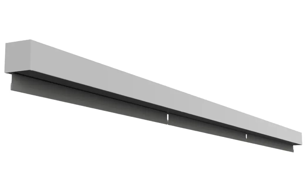
Remove the front fascia for diagnosis
With the fascia removed, you can easily see the roller, fabric, and end caps while operating the shade. This makes it much easier to identify where the noise is coming from.
Remove Nano V2 Box Fascia:
- Loosen the end cap screws on each end cap (REVERSE THREAD: turn clockwise to loosen)
- Hold the end caps level and push upwards on each side of the cassette face to unlatch
- You should feel and hear it disconnecting from the locking screw
- Pull the cover towards yourself, rotating upwards slightly to disengage
- Set fascia aside safely
Note: For battery shades, ensure the shade is in sleep mode before servicing. Lowering the shade to its limit before removal reduces fabric roll diameter for easier access.
With the roller exposed, operate the shade and observe where the noise is coming from.
Where is the noise coming from?
Operate the shade and listen carefully to identify the noise source.
Identifying the Source:
Motor Side: The end with the visible motor head (where motor attaches to tube)
Idler Side: The opposite end with the idler support
Fabric: Noise from the fabric itself (rubbing, scraping)
Motor side noise - what does it sound like?
Motor rotation/grinding noise
- Motor coming out of tube: Motor head may be slightly out of the tube (common with Open Roll/Pocket if brackets too far apart)
- Motor head attachment: Motor head may be loose on roller tube
- Dry components: Minor friction that can be resolved with dry lubricant
Note: Motor gears failing is extremely rare.
Check These Items:
- Bracket spacing (Open Roll/Pocket only): Brackets mounted too far apart can cause motor to come out of tube slightly, creating rotation noise. The ordered shade width is the correct bracket-to-bracket measurement
- Motor head security: Ensure motor head is firmly attached to roller tube and fully seated in the tube
- Apply dry lubricant: Apply a small amount of dry lithium or graphite grease to eliminate minor noises
Rubbing noise at motor end
Check for Contact Points:
- Fabric edge: Is fabric edge rubbing against motor head or end cap?
- End cap clearance: Is there adequate clearance between roller and end cap?
- Motor head position: Motor head should be centered, not tilted
Motor buzzing/humming
Some motor noise during operation is normal, especially:
- Light humming during movement
- Brief noise when starting/stopping
- Quiet mechanical sounds
Idler side noise diagnosis
- Idler pin needs lubrication: The idler pin may be dry causing friction noise
- End cap rubbing: Roller tube rubbing against end cap
- Cassette - idler not spring-loaded: For cassette shades, verify idler is still spring-loaded and properly seated in idler plate
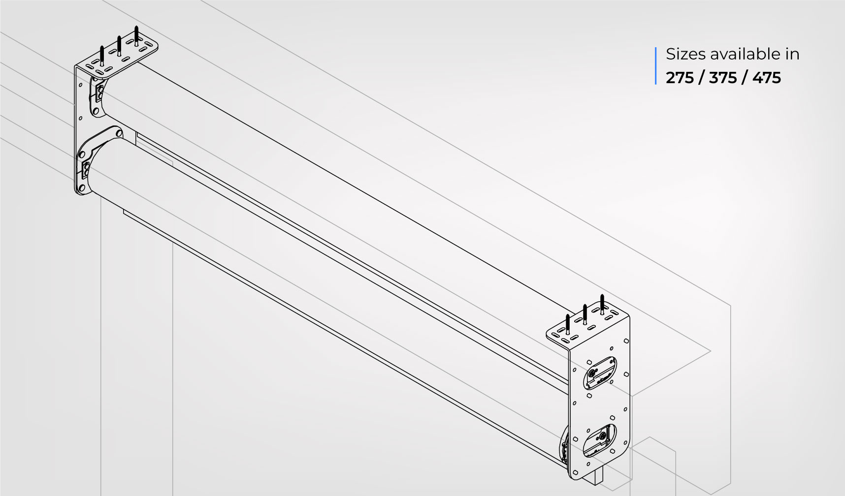
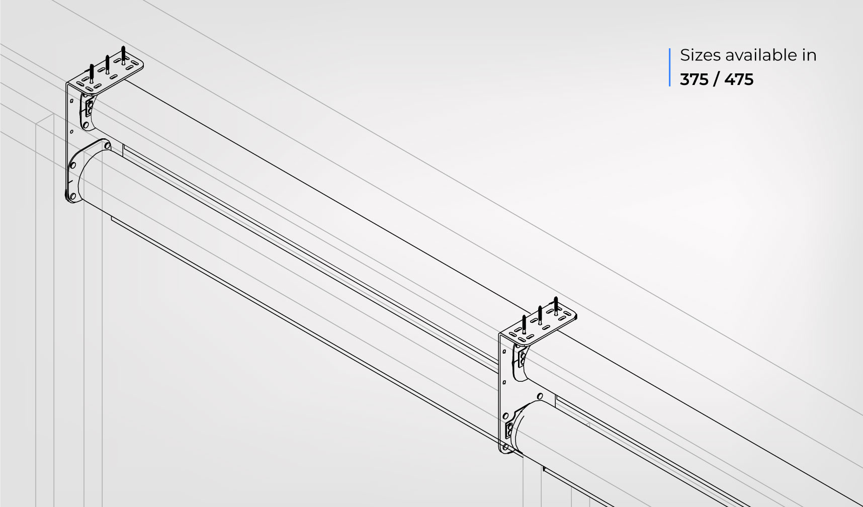
- Alignment issues (375/475 Nano Box): These shades have a leveling screw on the idler side endcap that can be adjusted for tube leveling, telescoping fixes, or alignment issues
Inspection Steps:
- Check idler movement: Idler should spin freely without resistance
- Look for rubbing: Tube should have clearance from end cap
- For cassette shades: Verify idler is still spring-loaded and seated properly in the idler plate
- For 375/475 Nano Box shades: Check the leveling screw on the idler side endcap for proper alignment
- Listen closely: Is it a squeak, grinding, or rubbing sound?
Idler noise - lubrication needed
If the idler is making noise, the idler pin needs lubrication. Apply a small amount of dry lithium or graphite grease to the idler pin.
DO NOT use wet lubricants - they can attract dust and cause long-term issues.
Idler Pin Lubrication Procedure:
- Access the idler - May require removing cover or end cap
- Clean the idler pin - Wipe away any existing debris or old lubricant
- Apply a small amount of dry lithium or graphite grease to the idler pin
- Rotate the idler manually to distribute lubricant evenly
- Wipe off excess - Only a thin coat is needed
- Test operation - Run the shade to verify noise is reduced
These shades have a leveling screw on the idler side endcap. If noise persists, check if the leveling screw needs adjustment for proper tube alignment.
Idler rubbing noise
Check Clearances:
- End cap gap: Should be small gap between roller tube and end cap
- Fabric edge: Fabric should not rub on end cap
- Alignment: Roller tube should be straight, not tilted
Fabric noise - describe the issue
Fabric rubbing on housing/edges
Fabric rubbing on the shade housing or edges usually indicates the roller is not properly aligned or the fabric is tracking off-center.
Correction Steps:
- Check roller alignment: Roller should be properly centered and level
- Inspect fabric tracking: Fabric should roll straight onto tube without drifting
- Look for telescoping: Is fabric drifting to one side?
- Verify clearances: Adequate space on both sides of roller
- For Box shades: Check cassette opening and ensure fascia is properly seated
- For Pocket shades: Check in-ceiling housing and ensure proper mounting
Side channel noise (Pocket shade)
On very wide shades, the roller tube can deflect (sag slightly in the middle), which may cause chevron patterns in the fabric or increased noise. This is typically noted during ordering and may include a fabric waiver.
Check Bracket Placement:
- Check shade width: Very wide shades may experience some tube deflection (this is material characteristic, not defect)
- Look for chevron patterns: Deflection causes V-shaped wrinkles in fabric
- Check fabric pressure: Fabric should glide smoothly in channels without excessive pressure
- Verify bracket spacing: Should match manufacturer specifications for shade width
Our tubes WILL NOT bow from improper bracket spacing. Tube deflection only occurs on very wide shades and is called out during ordering with a fabric waiver.
If experiencing binding/jamming, verify bracket spacing matches installation guide for your shade width.
Bracket spacing needs adjustment
For Pocket and Open Roll: The width the shade was ordered at is the bracket-to-bracket measurement. This is critical for proper operation.
Brackets too far apart: Motor can come out of tube slightly, causing rotation noise
Brackets too close together: Can cause binding noise and damage to fabric or fraying
Correction Steps:
- Verify ordered width: Check your order documentation for the exact shade width
- Measure bracket spacing: Current bracket-to-bracket measurement should match ordered width exactly
- Remove shade: Take down shade to access mounting brackets
- Reposition brackets: Adjust spacing to match the ordered shade width precisely
- Reinstall shade: Remount with correct spacing
- Test operation: Motor should be fully seated in tube, fabric should glide smoothly without noise or binding
Check channels for debris
Clean Side Channels:
- Fully deploy shade: Lower shade completely
- Inspect channels: Look inside both side channels for dirt, dust, or debris
- Clean channels: Use compressed air or soft brush to remove debris
- Check fabric edges: Ensure fabric edges are clean and not damaged
- Test operation: Raise and lower shade to verify smooth operation
Fabric flapping or wrinkling noise
- Wrinkles in fabric: Creases can make noise during rolling
- Loose fabric: Fabric not rolling tightly onto tube
- Improper limits: Fabric bunching at top or bottom
Nano Open Roll noise diagnosis
Open Roll shades have the roller exposed, making diagnosis easier. Common noise sources:
- Bracket spacing: Verify brackets are properly spaced per installation guide
- End caps: Rubbing on motor or idler side
- Mounting surface: Vibration transmitted to mounting surface
Open Roll bracket spacing
Note: Our tubes WILL NOT bow from improper bracket spacing. On very wide shades, tube deflection (slight sag) may occur and is noted during ordering with a fabric waiver.
Improper bracket spacing can cause:
- Binding or jamming
- Excessive friction during operation
- Noise from misalignment
Check and Correct:
- Visual check: Look at roller from the side - should be properly aligned
- Consult installation guide: Verify proper bracket spacing for your shade width
- Reposition if needed: Move brackets to correct spacing per specifications
Nano Pocket noise diagnosis
Pocket shades are in-ceiling recessed with no cassette. Let's identify where the noise is coming from.
Common noise sources for Pocket shades:
- Motor housing: Contact with in-ceiling mounting
- Fabric tracking: Fabric movement through opening
- Mounting vibration: Transmitted through ceiling structure
- Side channels (if installed): Optional accessory for fabric guidance
Describe the noise
Help Us Identify the Source:
Try these diagnostic steps:
- Operate slowly: Run shade at slowest speed to isolate noise
- Listen at different positions: Stand on motor side, then idler side
- Watch the roller: Look for visual clues (wobbling, rubbing, vibration)
- Note when it occurs: Continuous? Only when starting/stopping? At certain positions?
When was the shade installed?
Wrinkles from shipping are normal and typically relax over time.
New installation - wrinkles should relax
Minor wrinkles from shipping typically relax within 1-2 weeks after installation.
Give it time: Most wrinkles will naturally relax without intervention.
How to Help Wrinkles Relax Faster:
- Deploy the shade fully - Leave down for 24-48 hours in sunlight if possible to let fabric warm and stretch
- Cycle the shade - Run up and down 5-10 times daily to work out creases
- Use a garment steamer - Hold 6-12" away from fabric, never touch directly. Move slowly across wrinkled areas
NEVER use: Hair dryer, iron, or harsh chemicals on the fabric. These can damage the material permanently.
Describe the wrinkles
Help us understand the severity.
Wrinkles haven't relaxed after 2+ weeks
If wrinkles persist after 2 weeks, try these methods:
Wrinkle Removal Methods:
- Extended deployment in sunlight - Leave shade fully deployed for 5-7 days continuously, preferably in a sunny window to allow warmth to help relax the fabric
- Garment steamer - Use garment steamer at 12" distance, work slowly and methodically across all wrinkled areas. Multiple passes may be needed
Which direction is the fabric drifting?
Telescoping means the fabric gradually shifts to one side. Identifying the direction helps us fix it.
Fabric gradually shifts to one side during operation. If uncorrected, can lead to roll-overs and jams.
Is the shade level?
An unlevel installation is the #1 cause of telescoping.
Check Levelness:
- Place a level on top of the cassette or mounting brackets
- Check side-to-side level (not front-to-back)
- Verify both mounting points are at the same height
Is the shade level?
Level the shade first
Leveling Procedure:
- Adjust the mounting brackets so both are at exactly the same height
- Use shims if necessary to bring one side up
- Verify with a level across the top of the cassette
- Test the shade - run through a few cycles
Check the side channels (if applicable)
For Pocket shades, side channels can cause drift if misaligned or obstructed.
Inspect Side Channels:
- Alignment: Channels should be perfectly parallel and plumb
- Debris: Check inside channels for dirt, dust, or obstructions
- Fabric position: Fabric edges should glide smoothly in channels without binding
- Channel spacing: Both channels should be equidistant from shade center
What size is your Nano Box shade?
375 and 475 Nano Box shades have an idler adjustment screw that can help correct telescoping.
Adjust the idler screw
375 and 475 Nano Box shades have an allen screw on the bottom of the idler side end cap that adjusts tube alignment.
Look at the bottom of the idler side end cap (the end opposite the motor). You'll find an allen screw that raises or lowers that end of the tube.
Idler Adjustment Procedure:
- Locate the screw: Find the allen screw on the bottom of the idler side end cap
- Note the drift direction: Which way is the fabric telescoping?
-
Adjust the screw:
- If fabric drifts toward the idler side: Turn screw to raise that end of the tube
- If fabric drifts toward the motor side: Turn screw to lower that end of the tube
- Make small adjustments: Turn the screw 1/4 turn at a time
- Test: Cycle the shade several times and observe fabric tracking
- Repeat if needed: Continue adjusting until fabric tracks straight
The goal is to level the tube so fabric rolls evenly. Small adjustments make a big difference - be patient and test between each adjustment.
Try taping the tube
Adding tape to one side of the tube increases diameter slightly, helping fabric track straight.
Taping the Tube Procedure:
- Identify drift direction - Note which side the fabric is moving toward
- Add tape to THAT side - Apply electrical or painter's tape along the tube on the side the fabric drifts TOWARD
- Start with one layer - One strip of tape running the length of the tube
- Test - Cycle the shade several times and observe
- Add more if needed - Can add 2-3 layers total if necessary
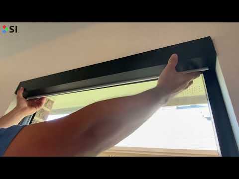
Is the fabric currently jammed?
Let's assess the situation first.
If the fabric is jammed, STOP immediately. Do not attempt to run through the jam - this can cause permanent fabric damage.
Stop the motor immediately
Step 1: Stop All Motion
- Press the STOP button on your remote or app
- If motor won't stop, disconnect power to the shade
- Do NOT force the motor to continue moving
Have you stopped the motor?
Access the fabric roller
Step 2: Get Access to the Jammed Area
For Box or Pocket shades:
- Remove the front fascia/cover to expose the roller tube
- You may need to loosen screws or release clips depending on model
For Open Roll shades:
- Roller is already exposed - access from front or above
Manually unroll the jammed fabric
Step 3: Clear the Jam Carefully
- Work slowly by hand - Rotate the roller tube backward to unroll fabric
- Guide the fabric - Keep it aligned as you unroll
- Watch for resistance - If fabric won't move, don't force it
- Remove obstructions - Clear any debris from the fabric path
- Fully deploy the shade - Unroll completely to straighten fabric
Inspect the fabric for damage
Step 4: Check for Issues
With the fabric fully deployed, look for:
- Tears or rips in the fabric
- Permanent creases from the jam
- Bent hem bar or damaged hardware
- Loose stitching at the edges
Does the fabric appear damaged?
Minor creases from jam
Minor creases from a jam often relax over time (1-2 weeks) with regular use. Follow the same wrinkle-relaxing techniques:
- Leave shade deployed for 24-48 hours
- Cycle up and down several times daily
- Maintain climate-controlled environment (65-75°F)
Prevent future jams - adjust upper limit
Most fabric roll-overs occur because the upper limit is set too high, allowing fabric to roll over the top of the tube and jam against the cassette.
Step 5: Set Upper Limit Correctly
- Reassemble the shade - Replace fascia/cover if removed
- Access limit settings - Via TRO.Y, remote, or Janus hub (depends on motor type)
- Lower the upper limit - Fabric should stop 1/4" to 1/2" BELOW the cassette opening
- Test multiple cycles - Verify fabric stops before reaching the cassette
Installation & Resources
Wiring Pinouts & Topologies
Reference diagrams for Nano motor wiring configurations.
For complete wiring pinouts and topologies, see: Nano Wiring Pinouts & Topologies
RS-485 Wiring Configurations:
Using 5-Conductor Wire:
Using CAT5/6 Cable:
Using 4-Conductor Wire:
RTS/Zigbee Wiring Configuration:
- 18-22 AWG recommended for most installations
- Shielded cable preferred in high-EMI environments
- Maximum run length: Consider voltage drop for long runs (50ft)
How to Fix Pin Holes in Blackout Material
Small pin holes in blackout fabric can allow light to pass through. Here's the simple repair method.
White-Out (correction fluid with brush applicator) - The blackout coating is white, so white correction fluid works perfectly.
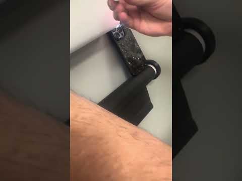
Repair Steps:
- Prepare the area - Lightly wipe around the pinhole with a clean, dry cloth to remove dust or residue
- Apply White-Out - Use the built-in brush to place a small drop directly over the pinhole. Avoid over-applying — a thin, even coat works best
- Allow to dry - Let the White-Out dry completely. If the pinhole still leaks light, apply a second coat once the first has dried
- Verify results - Hold the fabric up to a light source to verify the pinhole is fully blocked. Reapply as needed for full coverage
Identifying Your Motor Type
Quick Identification by Wiring/Connection
- 5 conductors (wires): RS-485 - connects to Janus hub, controlled via TRO.Y
- 2 conductors: Low Voltage Zigbee or RTS - power wires only
- Battery with thin antenna (bulbous tip): Wirefree Zigbee - TRO.Y/Helen or TaHoma
- Battery with thicker antenna: Wirefree RTS - Somfy handheld remote
- Ethernet cable: PoE (40 Series) - requires SI IP Bridge AND TRO.Y
SI Eco-System Troubleshooting
For issues with the control system, pairing/discovery, or third-party integrations, use our dedicated Eco-System Troubleshooting Wizard.
Get Support for Your Motor Issue
- Sales Order number (SHXXXXXX) or Project ID
- Shade size and fabric type
- Motor type (Zigbee, RS-485, RTS, or PoE)
- Short description of what is happening and what you've tried
- Photos or videos if possible
Report Physical/Fabric Issue
- Sales Order number (SHXXXXXX)
- Short description of the issue and what you've tried
- Photos showing the issue - REQUIRED
- When the shade was installed
- When the issue first appeared
Installation Questions
- Sales Order number (SHXXXXXX)
- Shade type and size
- Short description of what you need help with
- Photos of installation area if applicable
Issue Resolved
Here are some helpful resources for future reference:
Comments
0 comments
Please sign in to leave a comment.